After buying an active bass guitar (my first was a passive), I discovered that life would be a lot easier if the bass didn’t rely on a battery for it to work. This is because 9V batteries are expensive (well, ish) and nothing would be more annoying than finding that the battery has run out in the middle of a concert. I therefore decided to alter it a bit.
The Theory Bit
Broadly speaking, there are two ways of getting a signal from a bass. Firstly, you need a pickup of some sort which is usually a coil, but can also be a piezo-thingie which is cunning and also does the same thing. You can either run the pickup passively, which means that you take the mV signal caused by the vibration of the string above the coil, run it through a rheostat (volume control) and maybe a variable high-pass filter (tone control). You then chuck that down a cable to an amp. The other way of doing it involves using a 9V power supply to effectively power the pickups. Inside the bass is a preamp which amplifies the signal slightly, and also gives you a proper high/mid/low equaliser on the signal. Also, active basses are effectively noiseless, which is a good thing. The downside is that they’re more complicated, and need their battery changing every once in a while.
I decided I didn’t want to have to worry about having to change the battery and so wanted to come up with a method of powering the bass from an external power supply. I originally thought about drilling another connector hole into the back of the bass and running a 9V DC lead into that, but then I had a flash of inspiration in that I could take the power down the same cable that the signal goes down, much like how microphones pick up their “phantom power” of 48V DC.
So I built the blob box.
The Designy-Buildy Bit
The way a bass knows that it’s “on” is that the jack is actually a stereo jack, into which you plug a mono cable. This bridges two of the contacts and completes the power circuit turning the whole thing on. I realised that if I used a stereo cable and sent 9V between two of the pins, I could just take the battery out.
I went to Maplin (mainly because it’s just down the road) and picked up the following:
-
1x smallish aluminium box
-
2x stereo 1/4” sockets
-
1x mono power socket
-
1x 9V DC mains transformer
-
1x rather excessively large switch
-
1x 9V battery connector
-
2x 3mm 3.3V led’s - 1 red, 1 blue
-
A bit of wire
After doing a bit of testing, I found that the bass appeared to be wired backwards. Basically, the power pin of the stereo socket in the bass was at -9V compared to the ground pin. After building a few circuits, and a lot of thinking and shouting about why it didn’t work when you sent -9V down the cable to the bass, I realised that I was being stupid.
The reason it appeared to be backwards is that the switch was not sitting between +9V and the preamp circuit, but it sits between the preamp and ground. When you plug in a mono jack, you are actually providing a ground for the circuit, rather than power. This must make sense for some reason, but that escapes me. Anyway, after realising that I needed to send +9V DC down the cable, I found it actually worked.
A diagram would be really useful at this point, but I’ve got nowt to draw it in. Oh wait, there’s MS paint.
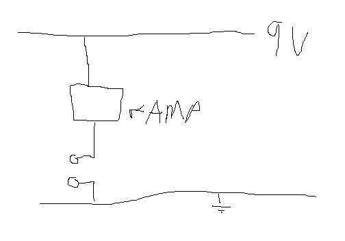
After realising this, I just had to short out the battery connector in the bass with the connector I bought, and then shove 9V down the cable. The circuit I built for the box looked something like this:
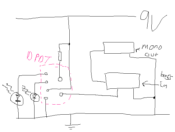
I’m sure that’s fairly self explanatory. There’s a DPDT switch, which switches on/off, with an LED for each state. Yes, there’s an LED to say that it’s off. Madness. I’d imagine if you were following this, you could use any colour you like. I used feeble red for off, and “HOLY CRAP THAT’S BRIGHT” blue for on, which I think works rather well.
After getting my trusty dremel out, and realising just how bad at dremelling I was, I made the necessary holes in the box and put everything together. Much to my surprise, it worked. The scratches around the switch and other bits on the photos are where the dremel slipped. Honest, I’m that bad. Anyway, have some pictures.
Pictures!!!!!! (Wow!!)
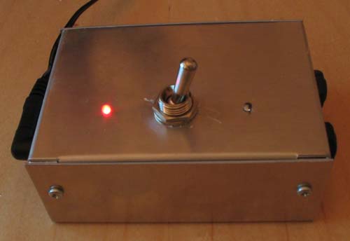
It’s off. So there’s a light to tell you so.
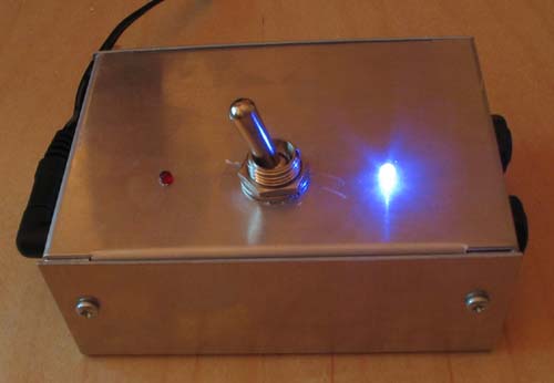
And now it’s on, and lighting the room up.
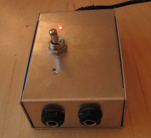
The 1/4” jack sockets on the side. I might label them at some point…